
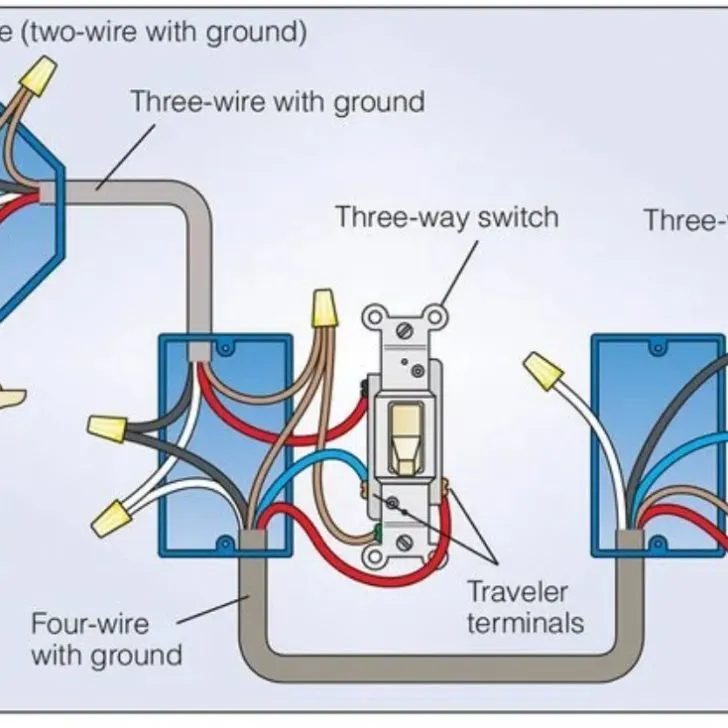
3-way switches are commonly used to control a light fixture from two different locations. They have three screw terminals for wiring connections, in addition to a grounding screw. Two of the terminals (usually lighter, brass-colored screws) take traveler wires that go from one switch to the other.
The third terminal, known as the common and is a darker color, serves one of two purposes depending on where it is positioned in the circuit run: Either it accepts the incoming hot wire from the power source, or it connects to the hot wire that leads onward to the light fixture.
Many aspects of the 3-way switch can differ drastically from the standard wall switch. It is therefore not uncommon for homeowners to have issues when dealing with 3-way switches.
In this article, we are going to show you how to wire 3-ways switches, as well as troubleshoot and resolve problems to do with these kinds of switches.
How to Troubleshoot a 3-Way Switch
While you do not need to troubleshoot a 3-way switch all the time, it may be necessary when the switches are not working.
Check this too: Ecobee Switch+ How to & Troubleshooting Guide
Assuming your bulb is in good condition and it is the switches that are not turning the lights on or off, or you have noticed that one of switches is bad, you have to troubleshoot. Another situation where you may need to troubleshoot is when the wires are not connected properly.
To troubleshoot a 3-way switch, follow these steps:
- Toggle the first switch. Turn the light on.
- Toggle the second switch. If you can turn the light on and off with this switch, this means that the switch is working.
- A defective switch will not be able to control a light that is already on.
- Leave this second switch with the light turned on.
- Now go back to the first switch. Turn it on and off. If it works, then the problem is not a defective switch.
- Otherwise, that is the defective one and will need to be replaced.
When replacing a defective 3-way switch, it is highly recommended you replace the two switches at the same time.
This is because it is assumed since both of them were installed at the same time, then the other is likely to fail any time soon as well. Here is how to replace a defective 3-way switch:
- First, turn off the power on the circuit breaker.
- Go to the switches and remove them.
- When you are able to access the wires, ensure that they are not touching nor are they close to each other.
- To quickly identify the wires, you can mark them or add an identifier so that you won’t get confused next time.
- Turn the power back on in the circuit breaker.
- Then, using a continuity tester check for ground on each wire. The ground wire is also called “hot” or “live” wire since this where the electricity flows.
- For a 3-way switch, there should only be one live wire, and that is the common wire. If you found the live wire on one switch, there should not be another live wire on the other switch.
- After you have found the live wire, go back to the circuit breaker to turn the power off.
- Install a new switch to the terminal with the live wire. Connect the live wire to the common terminal.
- Then, connect the traveler wires to the other two terminals. Close the new switch with all the wires inside.
- Now go to the second switch and take off the old switch.
- Look for the common wire by touching one of continuity tester’s probes to the wires. There should be a beep in one of those wires. The wire that beeps or registers a resistance is the common wire.
- Just like you did to the first terminal, connect the common wire to the common terminal. Then, connect the other traveler wires to their respective terminals.
- Attach the new switch to the wall with all the wires inside.
How Does a 3-Way Switch Work?
3-way switches are typically used to control a light fixture from two different locations. For example, a stairway or hallway might use a pair of 3-way switches at each end so that lights can be turned on when approaching one end of the stairway or hall, then turned off from the other end.
How these switches work is that when both toggles are up or both are down, the circuit is complete and the light fixture will be illuminated.
Otherwise, when the toggles are in opposite positions, the circuit is interrupted and the light fixture turns off. This allows either switch to control the on/off function of the light fixture at any time.
How is a 3-Way Switch Wired?
3-way switches can be wired in a number of different ways, depending on where they are located relative to the light fixture in the circuit cable runs.
For instance, they can be arranged so that the feed cable runs to the first 3-way switch, then to the light fixture box, then to the second 3-way switch.
They can also be wired so that the cables run through both 3-way switches, then to the light fixture. This is a more common configuration, in which the wiring connections are done as follows:
- At the location of the first 3-way switch, the feeder wire from the power source is a 2-ire cable with ground. This means there is a black hot wire, a white neutral wire, and a bare copper grounding wire.
- At this first switch, the black feed ire is connected to the common terminal screw on the switch. The grounding wire is connected both to the switch using a pigtail wire, and to the second cable run passing onward to the next switch.
- If the switchbox is metal, it also must be pigtailed to the grounding wires.
- The cable run connecting the two 3-way switches is made with three-wire cable. The black and red wires are “travelers” and are connected to the traveler screw terminals on the two switches, which is what allows the switches to turn the lights on and off in a flexible manner.
- Since switches don’t have white-colored neutral wire connections, the neutral wires at the boxes are simply joined together so they pass through, onward to the light fixture box.
- At the location of the second 3-way switch box, the wiring is the same as at the first switch, with the traveler terminals connected to the traveler wires coming from the first switch.
- However, at this second 3-way switch, the common screw terminal is connected to a black hot wire that leads onward to the light fixture.
- The white neutral wires, once again, are simply joined together, and the grounding wires are pigtailed together connecting the switch and to the box, if metallic.
- The cable run from the light fixture requires a to-wire cable with ground.
- At the light fixture, completing the wiring is simply a matter of connecting the black and white circuit wires to the matching wire leads on the light fixture.
- The ground wire is connected to the light fixture lead and is pigtailed to the box, if metallic.
Can You Wire a 3-Way Switch Wrong?
Improper wiring is one of the most common problems that homeowners face when installing/replacing their 3-way switches. This occurs when the circuit wires are connected to the wrong screw terminals. It is very easy to accidentally confuse the wiring of a 3-way switch when you are doing a replacement at home.
Can You Use a 2 Wire for a 3-Way Switch?
If you only have a two-wire cable to work with, you can still be connect a 3-way switching circuit for your garage or hallway, to enable you turn a light on and off from two different locations. You can purchase a couple of 4-way light switches and a couple of silicon diodes (1N1344, 1N1614, or equivalent) and connect them.
Two 4-way switches and two diodes wired back to back in a 2-wire circuit provide 3-way light control. If the light stays on regardless of switch position, reverse one of the diodes.
Two 3-way switches, four diodes, and two wires also enable 3-way switching. Observe polarity. Different switch manufacturers may locate and wire switch terminals differently.
How to Diagnose a Bad 3-way Switch
Usually when a 3-way switch fails, you are able to toggle the lights on and off at one switch but not the other. If one of the two 3-way switches toggles the light(s) on and off, the other 3-way switch has probably failed. To diagnose a bad switch, follow these steps below:
- Toggle each switch until the light comes on. Toggle one switch to see if it turns the light on and off. If it does, it is a good switch. Leave the light on.
- Toggle the other switch to see if it turns the light on and off. If it does, it is a good switch and the other is bad.
One of the 3-way switches will not turn the light on and off (while the light is on) and that is the bad switch.
After identifying the bad 3-way switch, test to verify it is bad and needs to be replaced.
How to By-Pass a 3-Way Switch
If your circuit contains two 3-way switches, follow the instructions below to bypass:
If the switch with the incoming “hot” is the one you want single control from:
- Replace that switch with a single-pole switch.
- Connect either of the traveler wires to the load side,
- Remove the other (unwanted) switch and connect the traveler wire used in step 2 to the “switched hot” wire that goes to the lights.
- The unused traveler wire is abandoned
If the switch without the incoming “hot” is the one you want single control from:
- Remove the switch with the incoming hot and connect the incoming hot to either of the traveler wires.
- Replace the other switch with a single-pole switch.
- Connect the traveler wired used in step 1 to one side of the switch.
- Connect the “switched hot” that goes to the lights to the other side of the switch.
- The unused traveler wire is abandoned.
Why would a 3-way Switch Not Work
There can be a number of reasons why a 3-way switch doesn’t work. Sometimes, one of the switches may have become defective. Also, someone may have tried to replace a defective switch and did not connect the wires properly.
If the issue is a defective 3-way switch, it helps to replace both switches at the same time. The reasoning here is: say you have one switch that has failed, how much longer will it take before the other one fails as well? Besides, it can be tedious trying to determine which of the two switches has become defective.
To replace a defective switch, first, you need to locate the common terminal. Once you do then follow these steps:
- Attach the common wire to the common terminal on the new switch. The remaining two insulated wires are attached to the remaining traveler terminals. Depending on your wiring, the bare ground wire is attached to the ground terminal on the metal frame of switch’s mounting ears. The common wire will be black and the travelers will be white if your wiring is up to modern codes.
- Next, screw the switches back into their boxes, put on the switch plate covers, and turn the power on to test the switches.
- If it doesn’t work, make sure you have connected the common wire to the common terminal.
How Do You Fix a 3-Way Improperly Wired Switch
If your 3-way switch is not working it can be frustrating trying to figure out how to get it to work again. Chances are the problem lies with the wiring, which may have happened when changing a 3-way switch and not gotten the wiring put back together right. Fortunately, you may not need to call an electrician to have this resolved. Fixing an improperly wired 3-way switch can be a DIY assignment you can do on your own.
For this, you will need the following things:
- Philips head screwdriver
- Flat blade screwdriver
- Electrical tester
- Wire nut
Then follow these steps to fix an improperly-wired 3-way switch:
- Start by turning off the power at the circuit breaker. Then remove the 3 wires from each of the switches and make sure that the wires are not touching anything.
- Set the electrical tester to the 120 volt AC (alternating current) setting.
- Turn the power back on at the circuit breaker. Locate the wire that is supplying power to the circuit by touching one of electrical tester’s probes to the ground (bare or green wire) and the other probe to each of the six wires one at a time until you get a 120-volt reading on the electrical tester. This is the common or hot wire. For identification purposes, screw a wire nut at the end of this wire. Turn off power at the circuit breaker once again.
- At the switch where you found power in step 3 above, put the other two wires you removed from the switch together and wire nut them.
- Set the electrical tester to the continuity or ohms setting and go to the location of the other switch. Touch the probes to the three wires removed from that switch until you get a reading on the tester indicating continuity. These are the circuit “runners”. Connect these wires to the switch, one wire on each of the brass-colored screws. The third wire is the common wire that feeds the light fixture and is connected to the dark screw on the switch.
- Go back to the first location and attach the single hot or common wire you had identified in step 3 to the dark screw on the switch. Connect the other two wires, one to each of the brass-colored screws on the switch.
- Replace both switches and covers.
- Turn the power on at the circuit breaker. Check the operation of your light. It should now work properly.
How to Test a 3 Way Switch Wiring
To test for voltage, follow these steps:
- Turn off the power to the circuit at the main panel. Disconnect all the three wires (or four, if the outlet is grounded) from both switches. Separate the wires so that they are as far away from each other as possible.
- Turn the power back on. Now, using a multimeter, you are going to determine which one of three colored wires is the “hot” wire. There should be only one hot wire in one of the two switch boxes. This is the common wire for that box.
- Set your multimeter to at least 110 volts. Hold one of the probes on a known ground, such as a bare ground wire or metal outlet box. Touch the other probe to the colored wires, one at a time. The wire that registers voltage is the hot wire, and the common wire for this box.
It is wise to also test the three colored wires in the other 3-way switch for voltage, if you haven’t already. There should not be any voltage, and you should not get a reading. If you get a voltage reading, this means that the switch is meant to control another light, appliance, or outlet. Maybe you are checking the wrong switch.
To test for continuity, follow these steps:
- Turn off power to the switches at the main panel and using a tester, make sure power is off.
- Remove the 3-way switches so you can access the switch terminals. You do not have to remove the wire connections.
- Using a continuity tester, check the continuity between the common (black) terminal and each of the traveler terminals (brass-colored) of each 3-way switch.
- There should be continuity between the common terminal and only one of the traveler terminals. After toggling the switch, there should be continuity between the common terminal and only the other traveler terminal.
Usually there will be no continuity between the common terminal and one (sometimes both) traveler terminals of one of the switches when a 3-way switch fails.
How to Use a 3 Way Switch with a Light Dimmer
With a 3-way dimmer, you can control the light with two switches. You will need a 3-way dimmer and a 3-way switch. This lets you dim from one location and turn the lights on and off from another.
If you are switching from two locations, you also need to use 3-way switches for both plain switches and dimmers. You can only have one dimmer per group. You can put the dimmer at either location, but not both locations.
Follow the instructions below to install and use a 3-way switch with a dimmer:
Remove the old switch
- Before touching the original light switch, turn off the power at your circuit box. Test the light switch afterward to make sure the electricity is off.
- Unscrew the switch plate and save it if you are reusing it. Most dimmers come with a plate to fit the new dimensions, but some are made to fit standard plates. Check the package of your new dimmer for dimensions to make sure it will fit.
- Open the dimmer switch and strip the rubber coating from the wires. To ensure a tight seal with the wall wires, expose at least 1-2 inches of copper wire.
- Remove the old switch from the wall, carefully unwrapping the wires from the rubber section. Test the wire using a voltmeter to check voltage levels.
Installing a 3-way switch
- Make sure electricity is turned off at the main circuit box before proceeding.
- Then, connect the ground wire to the corresponding wire on your dimmer. The ground wire is typically green or bare copper and should be connected to the bottom, center wire on your dimmer.
- Use a plastic wire cap to secure the two wires after wrapping, protecting the connection and ensuring a tight seal.
- Next, connect the red wire to the hot lead wire and cap them together. Usually they are marked red on the wall, but can be black or otherwise taped or marked off.
- Connect the two black (one wire may be red with a white stripe) wires to the traveler wires in your wall, typically marked with a white or black rubber finish.
- Finish with wire caps.
Check this too: Lutron Dimmer Switch Troubleshooting & How-to Guide
Install the new switch
- Push the wires into the box, being careful not to dislodge the connections and make space for the dimmer box.
- Screw the new box into the wall. Finish with the light plate included or replace the old light plate and screw tight.
- Ensure the switch is clear of any debris and turn on the electricity at the main circuit box. Test the new dimmer switch by turning it on and off, dimming as you go . Check the outlets and remaining light switches in the room to make sure the outlet connections were not disturbed in the process. For 3-way switches be sure to check the on/off switches at both light switches.